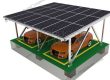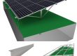
Installation steps for ground mounts SPC-GA20-4H-CW
Step 1: Pre-assembly and installation of purlin
When shipping, the factory has pre-assembled the purlin, jackets, columns, and grounding screws with bolts. After the bracket arrives on site, only need to open the pre-assembly, rotate the square tube in the direction on the drawing, and then remove the pre-assembled Bolts, lock the square tube on the base, and finally tighten all the bolts with a torque wrench.
1. Remove the pre-assembled paper wrapper or stretch film
2. Open the column in the direction of the arrow
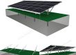
3.The front and rear columns are vertical to the ground after unfolding
4. Fix diagonal brace and jacket with bolt assembly
5. Fix the diagonal brace with the base with bolt components
6. Picture after assembly

Step 2: Fix the purlin pre-assembly
Put the assembled purlin pre-assembled on the ground screw, and install the pre-assembled base on the ground screw with M12*40 bolts.
Note: After installation, the front and rear columns are vertical to the ground. The connecting bolts of the front and rear columns and the base are at the lowest point. Try to make the bottom of the column contact with the base, so that the force on the bracket can directly act on the grounding screw. This position can also be adjusted when the upper surface of the purlin is not in the same plane.


Step 3 Adjust the purlin pre-assembly
According to the above steps, all the purlins are pre-assembled and installed on the ground screws. Note that after all the purlins are pre-assembled and installed on the ground screws, the front ends of the purlins must be on the same line. If they are not on the same line, you can Loosen the bolts fixed to the ground screws on the base, and fine-tune the entire purlins before and after pre-assembly, the upper surface of the purlin also needs to be on the same plane. If it is not on the same plane, you can loosen the bolts connecting the square tube to the base and fine-tune the pre-assembled bracket up and down.


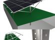
Step 4 install aluminum edge column
The aluminum edge column is installed on the rear vertical support square tube. The rear vertical square tube has pre-drilled holes. The aluminum edge column is fixed with M10 external hexagonal bolt
components. One square tube is installed on each of the front and back sides, and the two aluminum edge columns are cross-shaped, and one set is installed crosswise every other span.
The aluminum edge column is installed on the inner side of the square tube and fixed with hexagonal bolts
Installation complete picture of inner aluminum edge column
The aluminum edge column is installed on the outside of the square tube and fixed with hexagonal bolts
Installation completed drawing of the outer aluminum edge column
2 aluminum edge columns are crossed
Install a set of aluminum edge column every other span

Step 5 splicing beams
The steps of rail connection are as follows:
1. The length of the connecting piece is 300mm, and the depth of plugging the connecting piece into the
inner cavity of the track is 150mm
2. Fix the connecting piece with 2 self-tapping screws
3. Splicing the other rail
4. Fix the other track with 2 self-tapping screws
5. Side view of rail connection completed
6. Use the same method to fix the other side with self-tapping screws

Step 6 Determine the position of the beam on the purlin
According to the construction drawings, first connect two L4900 rails according to the above rail connection method. Then the cantilever is exposed by 700mm, and the distance between the front and rear of the purlin is 124mm, and then install a whole rail at an interval of 1013mm. The fixing method of the beam and the purlin is shown in the figure below


Step 7 Fix the beam
The beam is fixed with a crossbeam. There is a slot at the bottom of each rail. First put the spliced ?rail on the purlin. The placement position is as above. Put the pressure block sideways into the groove in the middle of the purlin, and then press the block Press down the groove at the bottom of the beam, and then use an Allen key to lock the pressure block tightly, press a beam fixing piece on each side of the rail

After the beam is fixed, the following picture is shown:

Fix the remaining 4 splicing rails on the purlins according to the above installation steps. After the installation is completed, the following picture is shown:

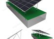
Step 8 install solar panels
According to the construction drawings, we can see that the solar panels are placed horizontally on the rail, from bottom to top, from right to left, or in the opposite direction. The solar panel frame on the outermost side exposes the rail 45mm, and the distance between the horizontal panels is 10mm. The position of the mid /end clamp is 940mm in the center, or adjust the position of the mid /end clamp according to the site


Step 9 Fix the solar panel with mid/end clamp
The solar panel is fixed by mid/end clamp, the two rails are fixed by end clamp, and the middle 3 rails are fixed by mid clamp . When installing, you only need to press the mid/end clamp to the side so that the block is locked into the groove of the beam, without sliding in from the side of the rail. There is a grounding clip on the mid clamp. The grounding clip needs to be pressed between the rail and the panel, and the bumps on the grounding clip can pierce the surface of the rail to conduct electricity.

Step 10 Fix the grounding clip
Use self-tapping screws to fix the grounding clip on the bottom of the rail, install one on each beam, and install each grounding clip in the same position. Then pass the copper wire through all the grounding clips, tighten the M6 ?bolts on the side of the grounding clip, fix the copper wire on the grounding clip, and finally lead the copper wire into the ground

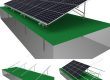
After the overall installation is complete, the following figure


More Good Quality Mounting Component Series can be reached at : www.SolarPartsComponents.com